AutoFEM Analysis is the friendly and easy-in-use software for finite element analysis
AutoFEM Analysis can be used by the broad community of engineers working in the field of mechanical and structural designing. You need not be a specialist in the finite element method in order to use AutoFEM Analysis. There are several asked-for modules, which allow for the solving of crucial problems for mechanical and structural engineering. They are as follows:
- AutoFEM Static Analysis module performs modeling of the stress state in mechanical structures and the testing of their strength;
- AutoFEM Fatigue Analysis module allows one to consider the influence of cyclic loading action on the strength and durability of a mechanical structure;
- AutoFEM Frequency Analysis module helps reveal natural frequencies (resonances) of structures and modes of oscillations;
- AutoFEM Buckling Analysis module determines critical loads of a mechanical system when the latter can be destroyed;
- AutoFEM Oscillations Analysis module finds an amplitude-frequency response of the structure;
- AutoFEM Thermal Analysis module solves various tasks related to the heat transfer.
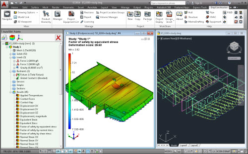
- AutoFEM & ShipConstructor integration module transfers the data from the ShipConstructor database onto finite-element model.
- AutoFEM Ship Buoyancy & Hydrostatics module calculates the strength of a ship floating in calm water.