AutoFEM Thermal Analysis
Using the AutoFEM Thermal Analysis module, any AutoCAD user gets the tool to calculate temperature fields inside mechanic structures. To carry out the thermal problem solving, the 3D model of the item is necessary, which is constructed directly in AutoCAD 3D, or imported into AutoCAD from the other CAD system.
AutoFEM Thermal Analysis permits to carry out the modelling of the thermal fields of two types:
- Stationary thermal fields (the stead-state regime) – the analysed system is steady-state and the temperature distribution does not change with time going on;
- Non-stationary thermal fields – the system is heating or cooling, and the temperature distribution is changing with time passing;
To set the conditions of calculation, different types of boundary conditions are available - temperature, heat flux, convective heat transfer, thermal power. After the calculation is completed, the user can analyse the results using the Post-processor of AutoFEM Analysis, as well as create the independent html-report containing the description of initial data and results of solving the thermal analysis problem.
Below you can find some examples of AutoFEM Thermal Analysis
|
Verification examples of AutoFEM Thermal Analysis |
|
|
|
|
|
|
|
|
|
|
|
|
|
|
|
|
|
|
|
|
|
|
Quick Start on AutoFEM Thermal Analysis
Welcome!
This lesson will help you to perform thermal analysis of the structure with the help of the AutoFEM Analysis Lite.
You will learn to: create a Thermal Analysis problem;
 create a finite element mesh;
 specify materials;
 specify thermal loads;
 perform calculation of stationary temperature fields (steady state regime);
 obtain results of calculation in the form of colour plots.
Download tutorial video of the AutoFEM Thermal Analysis Module
Create Study
Step 1: Create the Thermal Analysis Study
Open the example model to start work.
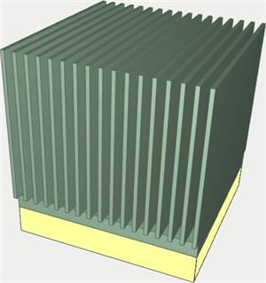
Let us calculate the temperature field for the radiator of the structure "microchip+radiator" shown on the picture. The temperature of the microchip's frame does not exceed 75 oC when the ambient temperature is 25 - 55 oC. For cooling the microchip, the aluminum-alloy radiator secured on the upper part of the microchip's frame is used. The microchip's frame is also made of aluminum for improving heat removal.
To create a Thermal Analysis problem, we need to:
1.Invoke the New problem's properties window using one of the following methods:
|
Command Line: |
FEMASTUDY |
|
Main Menu: |
AutoFEM | Create Study... |
|
Icon: |
|

2.Select the type of the study ( "Thermal Analysis" ) and add to the list ( "Selected Geometry" ) a solid:
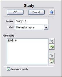
3.Since the option "Generate mesh" is activated, after setting up the problem, the system will automatically proceed to creating finite element mesh;
4.Press  for confirmation of New problem creation.
Create Mesh
Step 2: Create the Finite Element Mesh
After the problem setup, the system automatically proceeds to creating finite element mesh.
To create manually (or modify) the finite element mesh, we need to carry out the following sequence of steps:
1.Invoke the Mesh's properties window by one of the following methods:
|
Command Line: |
FEMAMESH |
|
Main Menu: |
AutoFEM | Create Mesh... |
|
Icon: |
|

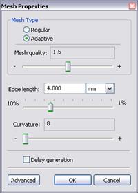
2.Let us build the finite-element mesh. The mesh quality will be set as 1.5 .The edge length of an element will be no greater than 4".000 mm .
3. Press for completing creation (or modification) of the mesh.
The result of mesh generation is displayed in the 3D window.
Instead of the original model, now you will see the image of the mesh. The original model is not shown at that moment.
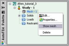
In case it is necessary to hide or display again the finite element mesh, choose the element "Mesh" in the service window "AutoFEM Palette" , then invoke the command "Hide Mesh" or "Show Mesh" from the context menu (by pressing  ).
).
Apply Thermal Loads
Step 3: Apply Thermal Loads
For the problem being considered let us specify the following thermal loads. We apply the load "Temperature" equal to 40oC to the bottom face of the radiator, and on the external heat-removing surfaces of the radiator we specify the boundary condition "Convection" with the heat transfer coefficient equal to 15 W/(m2 . oC), and the ambient temperature equal to 25 oC.
To prescribe the load "Temperature", we need to carry out the following sequence of steps:
1.Invoke the Load's properties window by one of the following methods:
|
Command Line: |
FEMATEMP |
|
Main Menu: |
AutoFEM | Loads\Restrains | Temperature... |
|
Icon: |
|

2.In the properties window of the "Temperature":
a) select the face for the load application;
b) specify the magnitude of the load and the units.
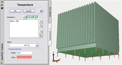
3.Press to confirm creation of the load "Temperature".
To specify the thermal load "Convection" we need to carry out the following sequence of steps:
1.Invoke the Load's properties window by one of the following methods:
|
Command Line: |
FEMACONVECTION |
|
Main Menu: |
AutoFEM | Loads\Restrains | Convection... |
|
Icon: |
|

2.In the properties window of the load "Convection":
a) select the loaded components - faces;
b) specify the heat transfer coefficient, the ambient temperature and the units.
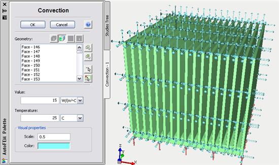
3. Press to confirm creation of the load "Convection".
Specify Material
Step 4: Specify Material
For each problem of the finite element analysis, it is important to correctly specify characteristics of the part's material.
To specify (or modify) the material, we need to carry out the following sequence of steps:
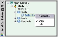
1.Invoke the material's properties window by choosing the solid in the service window "AutoFEM Palette" and performing the command "Material..."from the context menu (by pressing ).
2. Select a library of materials (into the group "Library");
3.From the list of materials, select, for example, "Aluminum Alloy 1060 ";
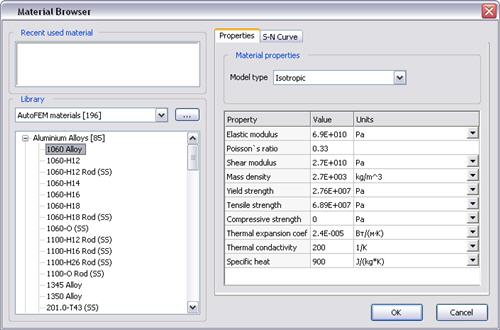
4.Confirm your selection by pressing .
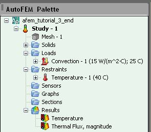
Working with AutoFEM Palette
Working with the "AutoFEM Palette" Window
All problems of the document and their components are shown in the service window "AutoFEM Palette" in the form of the structured tree. This window appears automatically after creating the study. If it is necessary, it can be closed or displayed again with the help of the command:
|
Command Line: |
FEMAPAL |
|
Main Menu: |
AutoFEM | Studies Palette |
|
Icon: |
|

The element "Study" combines all components and objects specified for performing the calculation: finite element mesh ("Mesh"), thermal loads ("Loads").
The folder "Results" is empty until calculation was successfully done.
Solve Study
Step 5: Solve the Thermal Analysis Study
After constructing the finite element mesh, specifying the loads and constraints, the calculation can be performed.
To solve the problem, the following sequence of steps must be carried out:
1.Invoke the solution's properties window by one of the following methods:
|
Command Line: |
FEMASOLVE |
|
Main Menu: |
AutoFEM | Solve... |
|
Icon: |
|

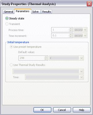
2.On the tab "Parameters", select the option "Steady state";
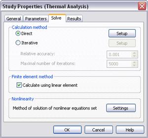
3.On the tab "Solve", in the group "Calculation method" select "Direct", and in the group "Finite element method" turn on the option "Calculate using linear element";
4.Press , to start the calculation.
Customizing Results
Customizing the Results
After successful solution of the Thermal Analysis problem, we need to analyze the obtained results.
The list of results available for viewing is shown in the problems tree in the folder "Results".
To extend the list of results shown in the problems tree, the user has to:
1.From the context menu popping up upon pressing on the name of the selected problem, invoke the window for customizing results (command "Results...");
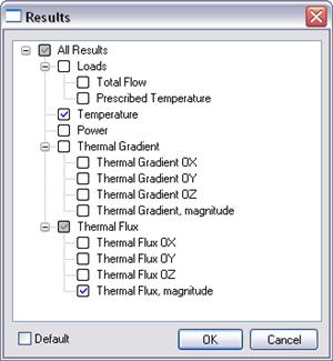
2.Check the results you need;
3".Press .
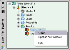
For viewing a result, select it with in the problems window and select the command "Open". You can also use  . The result will be shown in a window of the Postprocessor.
Analyze Calculation Results
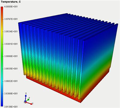
Step 6: Analyze Calculation Results
Open the result "Temperature". According to the results of the thermal analysis, the maximum temperature is no greater than 40oC at the temperature of the ambient space equal to 25 oC.
Generate Report
Step 9: Generate a Report
The user can create independent of the AutoFEM electronic documents which include the main information about the solved problem. The report is created in the html- format.
To create a report, the user needs to:
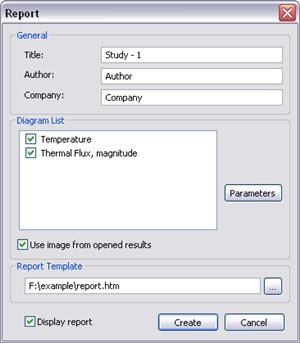
1.Invoke the dialog for customizing a report with the help of the command of the main menu: AutoFEM | Create Report...;
2.Fill in the fields in the group "General";
3.Tick the results, which have to be included in the report, in the "Diagram List";
4.Turn on the options "Use image from opened results" and "Display report";
5.Pressing the button  leads to appearance of the dialog for saving the report file.
Congratulations!
You successfully completed the thermal analysis of the structure with the help of the AutoFEM Analysis.