| AutoFEM Analysis Preparation of the calculation model | |||||||
| AutoFEM Analysis Preparation of the calculation model | |||||||
Generally, any ShipConstructor model drawing, i.e. an AutoCAD file that contains ShipConstructor parts (Planar Groups, Assemblies, Arrangements, etc.), can be used as the base FEA model. The ShipConstructor user himself creates the 3D models which will then be analysed by AutoFEM. There are several ways to prepare a 3D model for FEA by AutoFEM, such as:
Using the Product Hierarchy Drawing
Product Hierarchy drawings include ShipConstructor parts and can therefore be used for FEA by AutoFEM. However, they also contain data not used for FEA, and it may therefore be convenient to enable or disable certain portion of it.
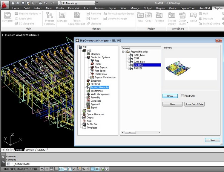
Product Hierarchy Drawing can be dedicated to group parts specifically for FEA
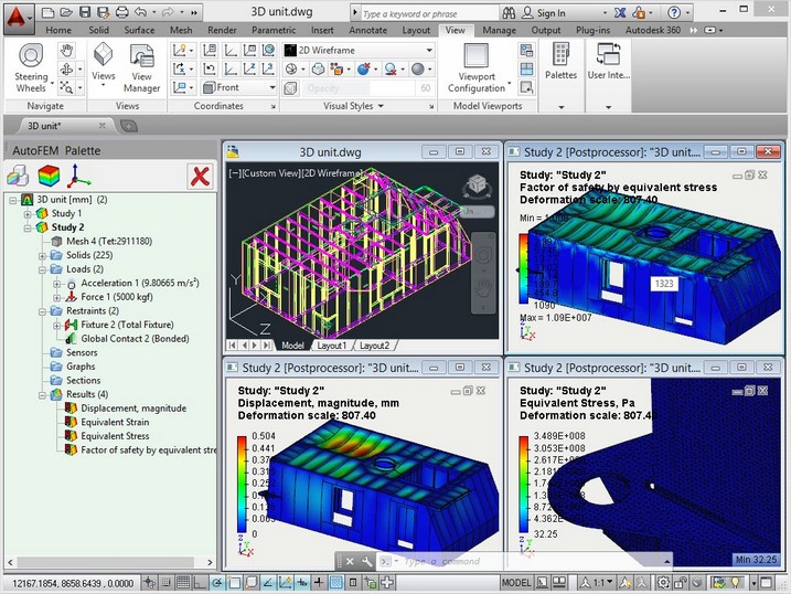
Using the Unit
A Unit drawing may also be used for FEA modelling.
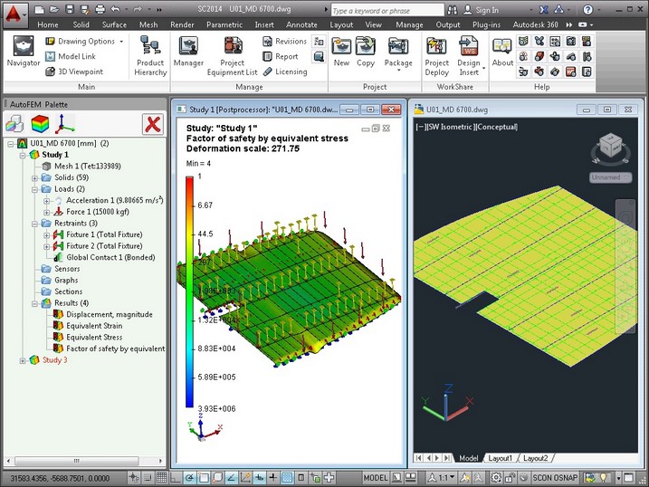
A FEA study addressing a Unit
Use of Assembly
Production drawing (Assemblies, etc.) may be used for finite-element modelling, too.
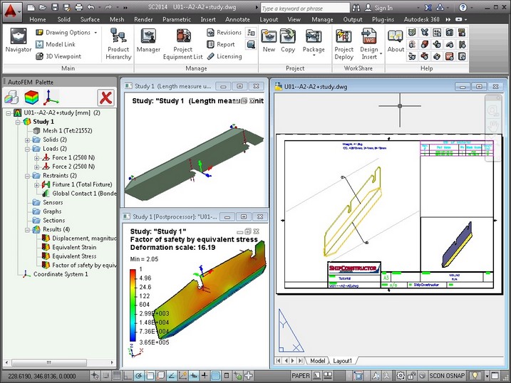
FEA carried out directly on a production assembly
Using the Model Link command
The user may combine several drawings and even Units to create a 3D FEA model, using ShipConstructor's Model Link.
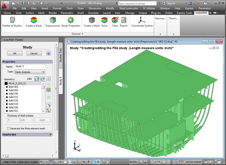
Creating a study encompassing several Units
"Exporting" the 3D model to "external" dwg files
Finally, one can even export a ShipConstructor model to a generic dwg format, and run the FEA outside the ShipCostructor environment.
Finite-element modelling of an "exported" ShipConstructor 3D model
Thus, the ShipConstructor user can choose the most appropriate strategy for his FEA purposes from a variety of options. But, in all cases, without ever leaving the AutoCAD 3D environment.
See also: Settings of integration with ShipConstructor