| AutoFEM Analysis Set of Objects for FEA: Options | |||||||
| AutoFEM Analysis Set of Objects for FEA: Options | |||||||
The command dialogue comprises the following basic options.
Measurement units of length. After opening the command palette, the user is able to select the measure units of length in which 3D model will be interpreted. On default, the units coincide with AutoCAD units of current DWG file. User is able to change these units not only while a set of objects is being created but at any time later in the same dialogue, changing the unit and the pressing the buttons Apply and Close .
Selection of the type of the set of objects for FEA
After defining measure units, one should select a type of the set of solids created. If only objects of one type (solids or surfaces) are present in the document, the system will automatically select the required type of the set of objects.
There are two variants (types) of the set of objects:
1) Set of AutoCAD solid bodies: the set of bodies consists of solid-body 3D AutoCAD models. The set of objects, consisting of 3D solids, is used:
• To create studies on the basis of tetrahedron finite elements, i.e. all types of finite-element problems in 3D setting.
• To create finite-element studies on the basis of triangular finite elements of shells and plates, where the modelled geometry is based on the facets of the 3D model consisting of 3D AutoCAD solids;
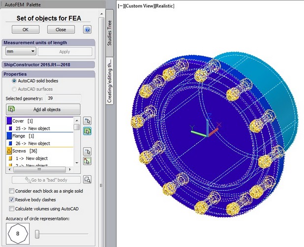
Palette of the command for creating the set of objects for FEA (3D solids)
2) Set of AutoCAD surfaces: the 3D model consists of surface objects of AutoCAD (surfaces, nurb-surfaces). This set of objects for modelling is used for finite-element modelling of structures, the behaviour of which can be modelled with the use of 2D triangular finite elements of the first and second degree of approximation (i.e. linear and quadratic triangular finite elements).
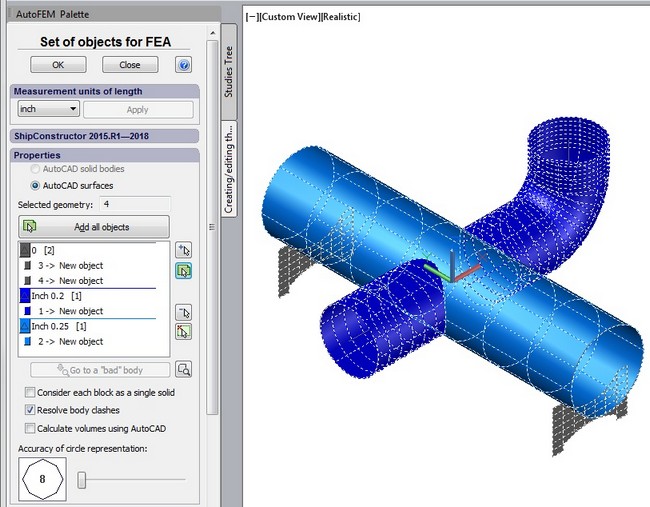
Palette of the command to create the set of objects for FEA (3D surfaces)
Additional options
Resolve body clashes (default: on) - detects and corrects the intersections between bodies if they are in the 3D model. If the study is created for an assembly model and several bodies have been selected, the system will check these bodies for intersection. If the check finds the intersecting bodies, the system will analyse the geometry of the assembly model and automatically remove the intersecting areas only from the calculation model. The initial AutoCAD 3D model is not changed. Use of this option may be recommended for assembly structures because a lot of them have an inaccuracy in construction and often have so called "body clashes". The latter can produce geometrical errors for mesh generation process or falsify the calculation results because, obviously, two or several different bodies are not capable divide the same space volume in reality.
Calculate volumes using AutoCAD - provides the automatic calculation of volumes (for 3D solids) and areas (for 3D surfaces) during the process of retrieving the geometry from AutoCAD. These data might be used later to verify the accuracy of the geometry representation by the finite elements (see Physical Properties of Objects).
Accuracy of circle representation - defines an accuracy of a round shape approximation of a 3D model geometry for visualisation purpose in the Preprocessor window.
See also: Set of objects for FEA, Selecting AutoCAD Objects, Working with AutoCAD layers, Working with AutoCAD Blocks, Treatment of Errors