| AutoFEM Analysis Bar Loaded with Sinusoidal Force on the Free End | |||||||
| AutoFEM Analysis Bar Loaded with Sinusoidal Force on the Free End | |||||||
Bar Loaded with Sinusoidal Force on the Free End
Let us consider longitudinal vibrations of a steel beam. Its left end is fixed. Longitudinal force is applied to the right end starting from time t = 0. The force changes under the law P=P0∙sin(ωt).
|
It is necessary to define the maximum displacement of the beam end.
Beam length l=0.5 m. Cross-section is rectangular with height h=50 mm and width b= 20 mm. Modulus of elasticity E=200 GPa, Poisson ratio ν=0.29, density ρ=7900 kg/m3. Amplitude and frequency of external force are correspondingly equal P0=10 kN and ν0=ω/2π=2 kHz.
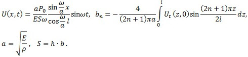
Displacements of the beam are determined by the formula:
![]()
where
Limited by six terms of series (n=0…5) we create a graph of sections displacements from time t on ten intervals of external force. The sections have the following coordinates x=l (right beam end), x=0.75l, x=0.5l and x=0.25l .
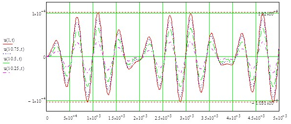
Displacements of beam sections
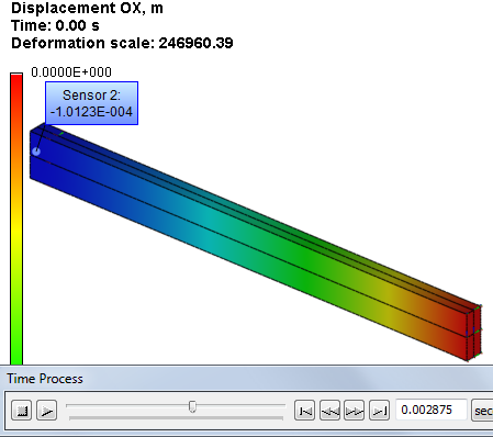
Maximum displacements appear on the right end of the beam and are under tension 1.02E-004 m, under compression -1.031E-004 m.
Let us calculate AutoFEM Analysis study: We create two studies, one Transitional processes, another Mode superposition with the same loads and restraints.
|
The finite element model with applied loads and restraints |
We create a full restraint on the left butt end of the beam. The right end will stay free. We apply distributed force to the free end and specify its value using graph:
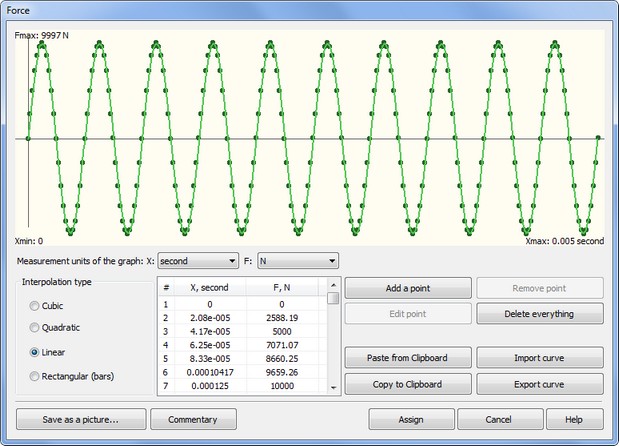
For both of the studies, we set the finite modeling time 0.005 s, the time step of integration 5∙10-6 s. The method of time integration: Newmark. We set a number of the lower natural frequencies in the Mode superposition study: 5.
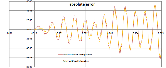
Let us find the step on which the maximum deviation by graph appears after calculation using AutoFEM Analysis:

After carrying out calculation with the help of AutoFEM, the following results are obtained:
Table 1.Parameters of the finite element mesh
Finite Element Type |
Number of Nodes |
Number of Finite Elements |
quadratic tetrahedron |
809 |
2645 |
Table 2.Parameters of temporal discretization
Total calculation time (s) |
Time step (s) |
Number of time layers |
5E-003 |
5E-006 |
1001 |
Table 3. Transitional processes, Result "Displacement, OX"*
Numerical Solution |
Analytical Solution |
Error δ =100%|w* - w| / |w| |
1.0180E-04 |
1.02E-004 |
0.19 |
Table 4. Mode superposition, Result "Displacement, OX"*
Numerical Solution |
Analytical Solution |
Error δ =100%|w* - w| / |w| |
1.0123E-04 |
1.02E-004 |
0.78 |
|
Conclusions:
The maximum displacement of the free end of the beam, found using AutoFEM Analysis is: for the Transitional process 1.0180E-04 (relative error 0.19%), for the Mode superposition 1.0120E-04 (relative error 0.78%).
*The results of numerical tests depend on the finite element mesh and may differ slightly from those given in the table.
Read more about AutoFEM Static Analysis